Resources
I/O Resources
The Resources View combines all the worksheets required for firmware resource allocation,
configuration and I/O monitoring.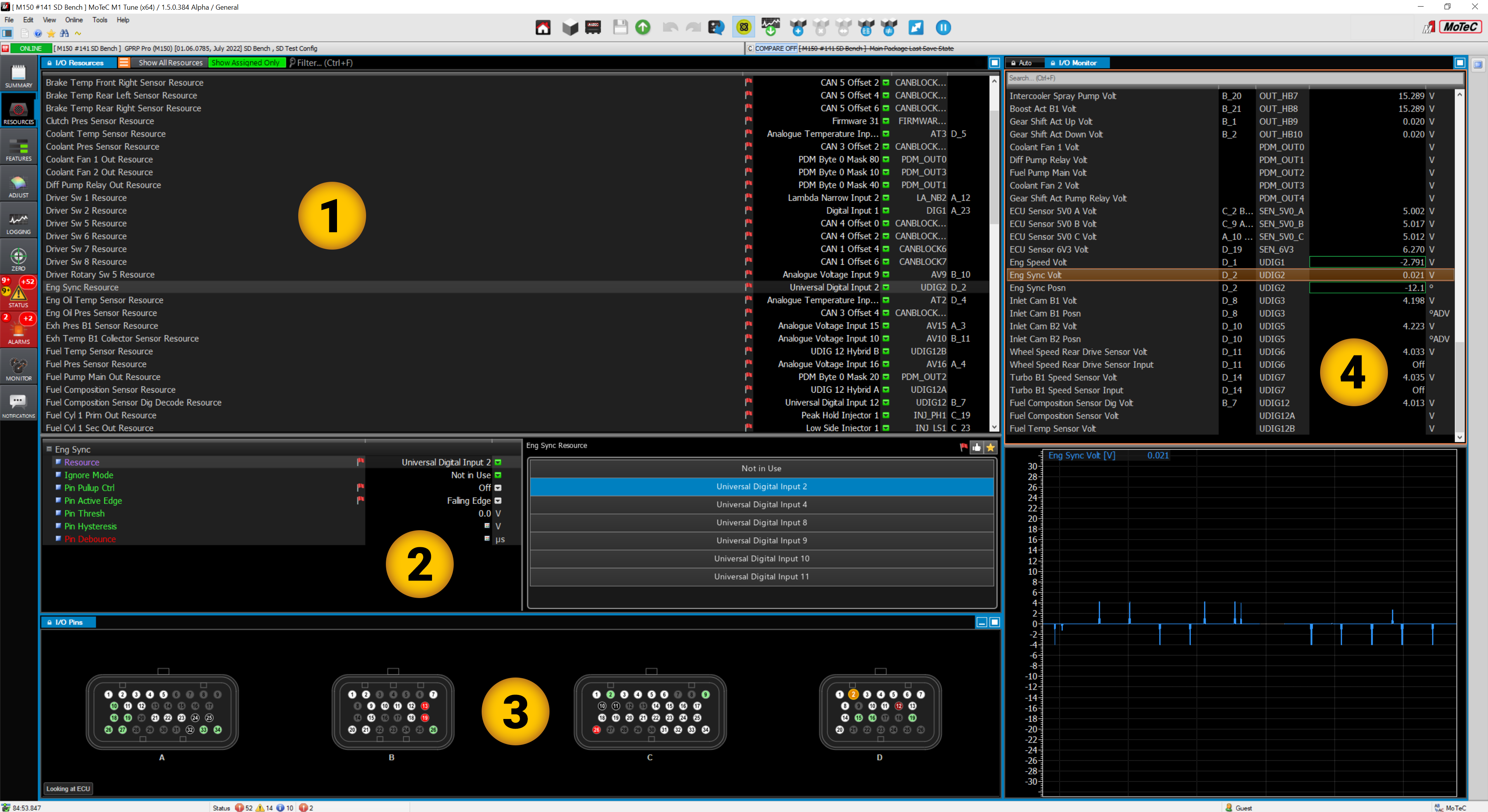
- 1 I/O Resources view.
- 2 Details view.
- 3 I/O Pins view.
- 4 I/O Monitor view.
The I/O Resources worksheet lists the Resource name, Pin name, Pin designation and Pin number.
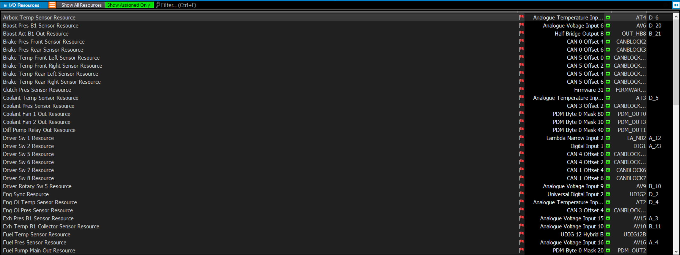
The displayed resources can be toggled between Show All Resources available in the firmware to Show Assigned Only.
The Filter section (Ctrl F) can be used to quickly find a resource from the list.
The Hide/Show Details toggle ![]() will show/hide the details view at the bottom of the I/O Resources
worksheet.
will show/hide the details view at the bottom of the I/O Resources
worksheet.
![]()
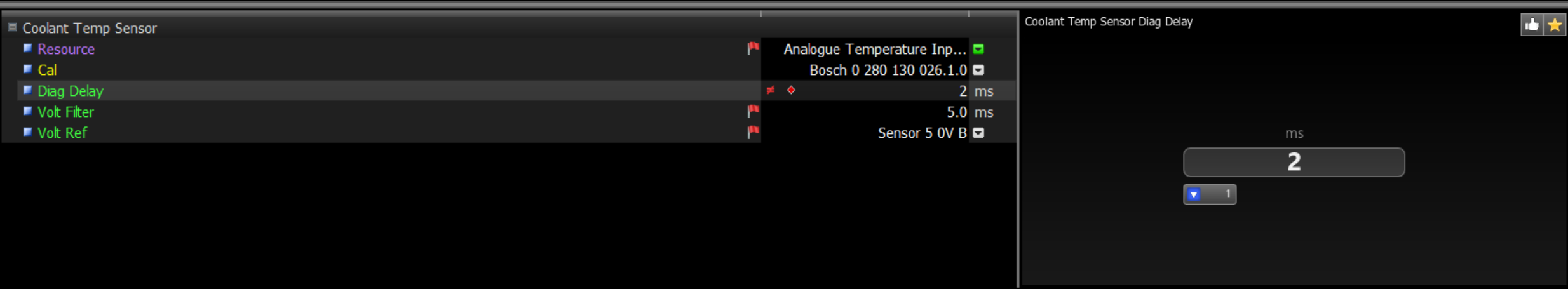
Details View
The Details View shows the configuration details for each resource selected in the Resources worksheet.
I/O Pins
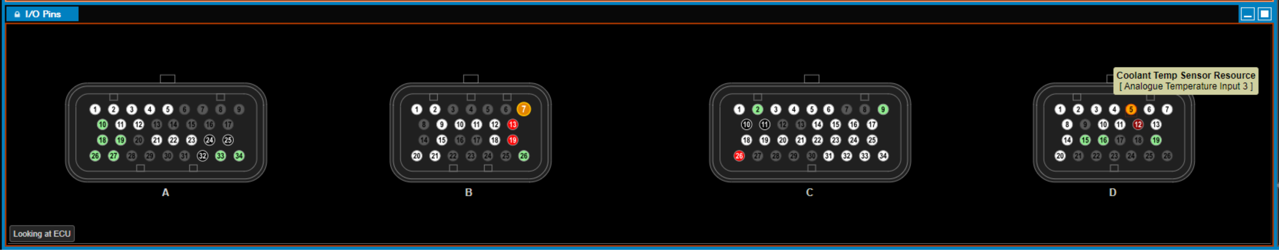
 White = assigned input/output resource pins.
 Green = Common sensor 5v and 0v pins.
 Red =
12v pins.
Red =
12v pins. Black = Ground pins.
 Orange = Currently selected pin.
- Hovering the mouse pointer over an assigned pin shows the Resource assigned and the pin name.
- Hovering the mouse pointer over a greyed out pin shows the pin name.
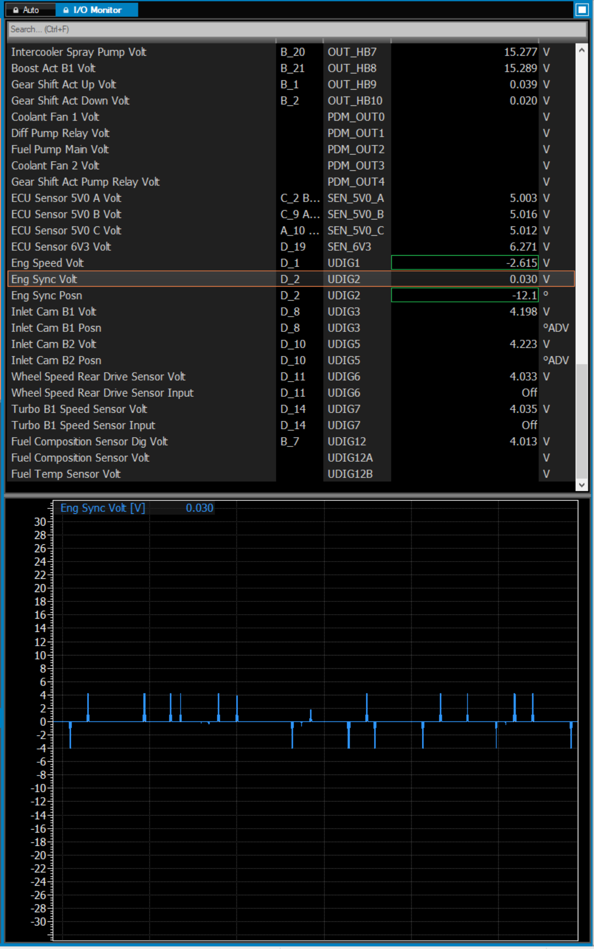
I/O monitor
The I/O Monitor view displays the assigned resources, input and output values in the upper section. The lower section displays a time graph specific to the selected resource.
The Auto view within the I/O Monitor displays the relevant channels based on the resource selected.